Design of explosions
Open-pit explosions
An open-pit explosion in Kola mine is usually arranged as follows: many shallow holes are drilled and explosives are placed there. Number of the holes can amount to several hundred, their depths may be several dozens meters. Some of holes are connected to constitute delaying phases i.e., sets of holes which are exploded simultaneously. Sometimes delaying phases may consist of one or two holes. Usual delays between exploding phases are 20, 40 and 60 ms.
Explosion in Koashva quarry of Vostochny mine (Khibiny Massif) 04.07.2003. Time of detonation start is 7.45:22 GMT. Total weight of explosive material was 46480 kg exploded by 19 delaying phases with delays 20 ms. Thus, total explosion time is 380 ms, sequence of exploding is shown in figure below. Weights of explosives per delaying phases are given in the table.
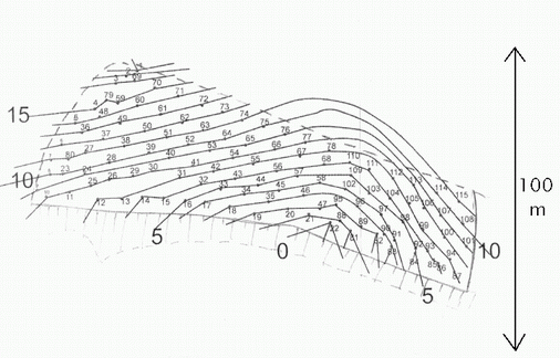
Plan of 04.07.2003 explosion. Numerated points are holes, solid lines which connect them are delaying phases. Detonation of the explosion started from 0 phase which consisted of a single hole.
Weight of explosives per delaying phase
| Phase | Weight (kg) | Phase | Weight (kg) | Phase | Weight (kg) |
| 0 | 489 | 7 | 5273 | 14 | 1522 |
| 1 | 1413 | 8 | 5382 | 15 | 1468 |
| 2 | 2716 | 9 | 3153 | 16 | 707 |
| 3 | 2664 | 10 | 3479 | 17 | 435 |
Underground explosions
The simplified scheme of a typical underground explosion is shown in Fig. U1. An ore block to destroy is divided onto two (sometimes three) parts by intermediate horizon or horizons. These parts (subblocks) are slightly shifted with respect to each other. Series of "fans" of holes are drilled in each subblock and charges are introduced there. These "fans" are arranged on parallel planes inside the subblocks. To drill them horizontal drifts are used.
Every such a plane is a single delaying phase, i.e., all charges situated there are exploded simultaneously. Usual order of the exploding is also shown in Fig U1. (the capitals A, B, C, D, E marking the planes) : charges introduced into the projecting part of the down subblock are exploded the first (A), the corresponding parts of all subblocks (B, C, D) are next and the overhanging part of the upper subblock is exploded the last (E).
To output the destroyed ore a set of finger-like funnels is prepared beneath the block. The ends of the funnels are directed to a haulage ort from which the ore is removed by trolleys.
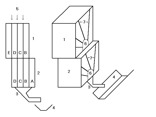
Simplified scheme of a typical underground explosion. 1,2 - ore subblocks; 3 - finger-like funnel; 4 - haulage ort with trolleys; 5 - parallel planes with charges; 6 - horizontal drifts used to drill "fans" of holes and insert explosive material; 7-"fans" of holes with charges arranged on parallel planes (5); A-E - delaying phases, 8-intermediate horizon separating ore blocks. Dimensions of an explosion which are used in tables are shown by arrows.
In tables below we shall indicate sizes of explosions as shown in the Fig.U1. and number of intermediate horizons separation ore blocks (for example, the explosion in Fig.U1 has one intermediate horizon).
1. 24.03.2002
| Date: | 24.03.2002 |
| Detonation time (GMT): | 4.13:22 |
| Coordinates: | 67.662 33.752, h=380 m |
| Mine: | Kirovsk, Yukspor add-on |
| Sizes: | |
| Length, m: | 64 |
| Height, m: | 90 |
| Width, m: | 25 |
| Number of intermediate horizons: | 2 |
| Kind of explosive: | grammonite 79/21 |
| Total weight of explosive, kg: | 200,125 |
| Exploding method: | electrical |
| N delaying phases: | 18 |
| Delays, ms: | 23 |
| Total exploding time, ms | 391 |
| Weight of destroying ore, ton: | 484,154 |
| Total length of holes, m: | 32,995 |
Amounts of explosive material (EM, kg) per delaying phases
| Phase | EM | Phase | EM |
| 0 | 18,854 | 9 | 6,595 |
| 1 | 9,478 | 10 | 11,283 |
| 2 | 3,657 | 11 | 6,622 |
| 3 | 19,295 | 12 | 13,818 |
| 4 | 19,151 | 13 | 5,973 |
| 5 | 15,278 | 14 | 12,895 |
| 6 | 17,511 | 15 | 6,007 |
| 7 | 6,731 | 16 | 5,963 |
| 8 | 15,045 | 17 | 5,969 |
| Total | 200,125 |